Furuno Radar Wiring Diagram
12 Volt 2 Way Switch Wiring Diagram, How to wire LED Lights & Use 2-Way switches | 12 Volt Planet, 7.8 MB, 05:41, 128,538, 12 Volt Planet TV, 2019-03-07T10:24:09.000000Z, 19, 12v Switch Wiring, www.chanish.org, 600 x 555, jpeg, 12vdc oznium volts dimmer chanish, 20, 12-volt-2-way-switch-wiring-diagram, Anime Arts
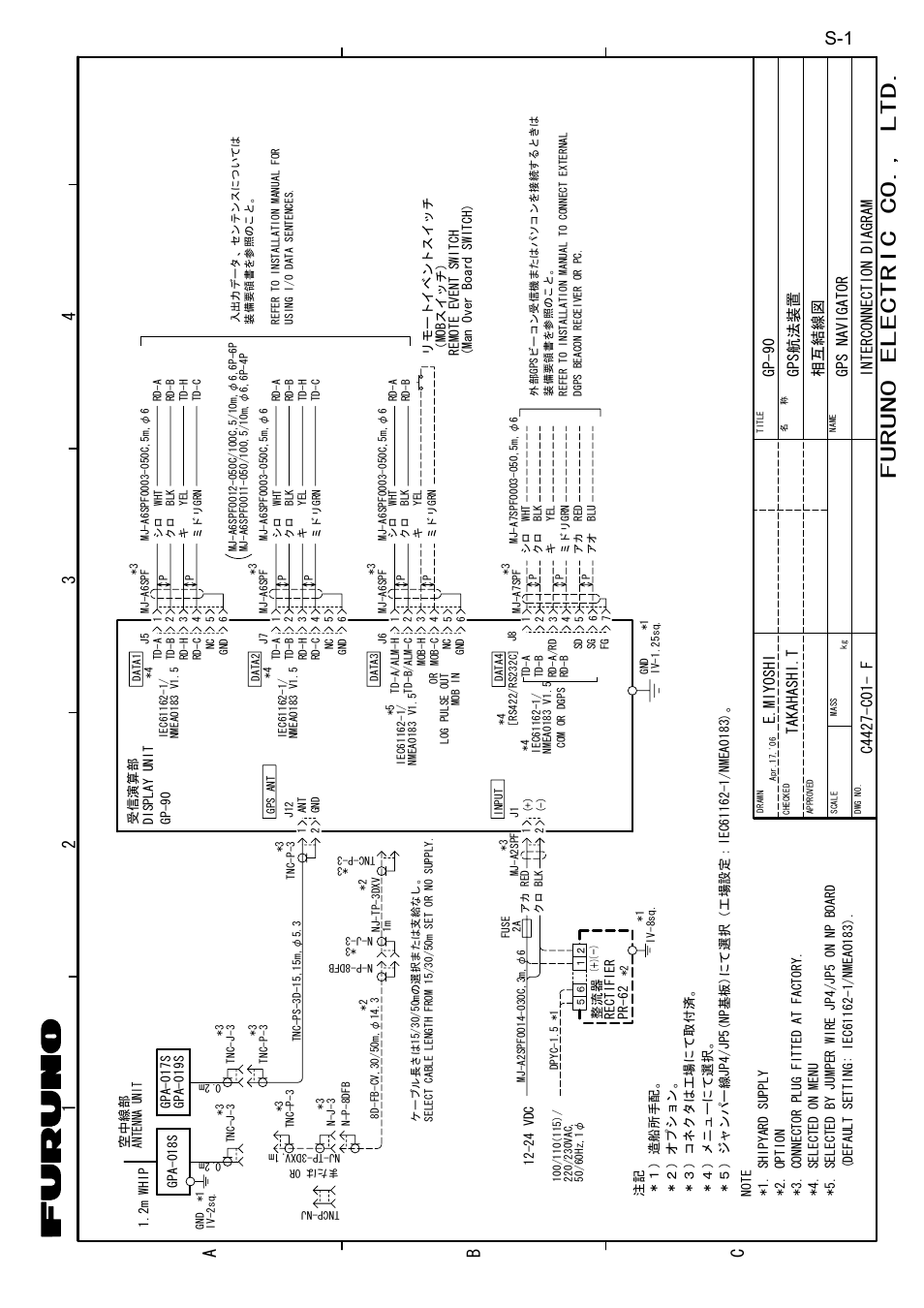
Furuno europe b. v. Ridderhaven 19b, 2984 bt ridderkerk, the netherlands program no. Power supply 12/24 vdc radar sensor drs4dl Furuno usa supplies nmea approved components as follows.
Nmea2000 backbone cable, 6m 1 ea. One chip radar detection circuit under sensor circuits 12298 next gr diy infrared system arduino project using ultrasonic techatronic proximity detector simple diagram cw doppler block advantages applications limitations concepts ece 480 team 5 interactive demonstration basic fundamentals frequencies and powers sensing ultra wideband design implementation. I just aquired a furuno 1720 radar system for my 23 ft sea ox w/a. I have the connecting cable and all wires, but my issue is that the radar cable just has bare wirez on the dome end and i don't know where they go. Any ideas where i. Hi i have a furuno 1900 with a open array, system works and array goes around but doesnt recieve signal i notice that theres three wires cut from when it was remove and i believe those are for the signal does anyone have a diagram for this for if csomeone can tell me where to hook up those 3. Two lines through the wiring clamps (c) to (e) to two of connectors j708, or j710. For cable for “input” signal of an external radar, connect to j710. • install the radar sensor on radar arch, on a mast or on an appropriate platform.
19" RADOME RADAR SENSOR DRS2D | Marine Radar | Products | FURUNO
Furuno 1623 Wiring Diagram

Rd33 Furuno Wiring Diagram

12.1" MARINE RADAR FR-8122 | Marine Radar | Products | FURUNO
4' OR 6' OPEN RADAR SENSOR DRS25A | Marine Radar | Products | FURUNO
Furuno Nav Netvx2 Wiring Diagram
Rd33 Furuno Wiring Diagram

Stampidoe Blog

Furuno 1623 Wiring Diagram

Furuno 1623 Wiring Diagram

